


Instruments For Testing Your Innovations


High Voltage Function Generator
Function generators are commonly used for lab bench testing. For some lab testing and scientific experiments, these commonly available function/signal generator output voltage is about +/-
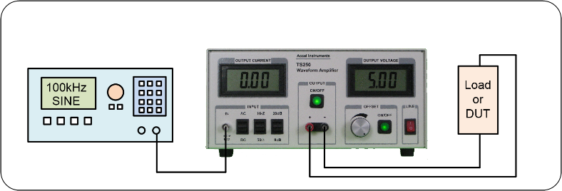
Figure 1. Combine TS250 Waveform Amplifier to makes a high-
High Voltage Function Generator Connection
Function Generator
- Function Generator Power Amplifier
- High Voltage Pulse Source
- Power Supply Transient and Noise Simulator
- Piezoelectric Transducers and Sensors
- Electrochemical Cells and Plating
- MEMS Devices
- High Speed Relays
- High Speed Solenoid Valves
- High-
Frequency AC Magnetic Field - Plasma Generation
- Research and Development
- Scientific Experiments
High Power/Voltage Function Generator Applications
High Output Current and Low Output Resistance
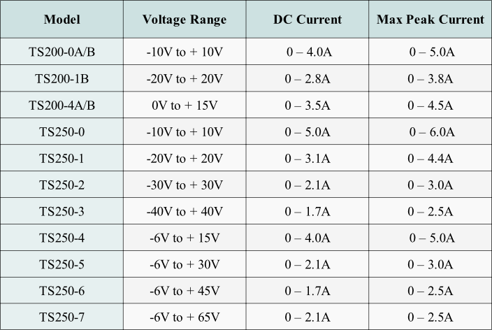
Conventional signal generator output resistance is 50 ohm. This 50 ohm output resistance severely limits its output current to about 100mA. The TS250/TS250 amplifiers has very low output resistance (~50 mOhm). Their output current is up to 6A, depends on the model. See the Selection Guide below for output current and voltage range. Using a waveform generator and an amplifier combination (Figure 1) offers flexible output power/voltage/current over a single unit high voltage signal generator for many bench testing applications.
Further Increase Output Current
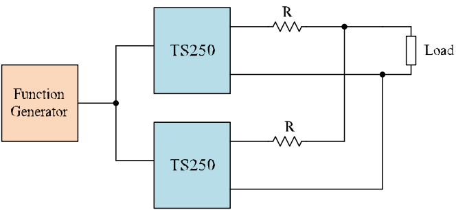
Another use for using external driver amplifier is it can increase the output current by connecting multiple amplifiers in parallel. Very high current is sometimes necessary for some experiments such as driving magnetic coils. As shown in Figure 2 below, 2 or more TS200/TS250 high-
Figure 2. High power function generator uses two TS250 drivers for higher output current.
Advanced Techniques
Obtain Higher DC Offset Voltage
Some test applications require high DC bias voltage. In such applications, this requires high DC bias voltage, but low DC current. For example, in power supply ripple testing applications, the DC input may be up to 100V, but the input ripple voltage required for this test is only 1Vpp. The unit under test (UUT) has large input capacitance and at high frequency (100kHz), it will required +/-
By the use of the TS250/TS200 Waveform Amplifier and an isolated DC power supply, a high-
DC power supplies have internal capacitors. Adding additional external bypass capacitors is recommended. This is especially true for high frequency waveform. Multiple capacitors with various capacitance that are connected in parallels offer better frequency response. Using low ESL and ESR ceramic capacitors is the best, but a combination of tantalum, electrolytic, and ceramic capacitors are okay. The external bypass capacitance must be high enough so that its impedance is at least ten-
To produced the required waveform, the external isolated DC power supply is used to set the DC or nominal voltage. The amplifier driver produces the AC voltage signal. The AC amplitude is set by the function generator and the TS250/TS200 gain. For instant, a piezo transducer requires a 100V bias DC voltage as well as a 80Vpp sinusoidal. This is same as 60V to 140V sinusoidal swing voltage. This is accomplish by setting the external DC voltage to 100V, set the TS250 gain to 20dB, and set the function generator voltage to 8Vpp (+/-
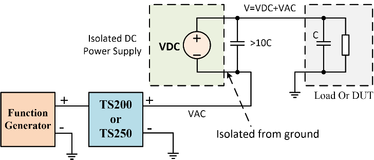
Figure 3. Using an external isolated DC power supply connected in series with an high-


Quick Links
Copyright: High-
Table 1. High-Voltage Signal Generator Amp Selection Guide
Select a Signal Generator
The TS250/TS200 are designed to interface with most function generators as well as signal generators. These high voltage function generator amplifiers inputs are using BNC female connector. They use standard 50-
|
Manufacture |
Model |
Features |
|
Rigol |
DG1022 |
Low- |
|
BK Precision |
4014B |
Low- |
|
Tektronix |
AFG1000 |
|
|
Keysight |
33220A |
20MHz |
|
Keysight |
33250A |
Variable slew- |
Table 2. Signal Generator Selection Guide

High Voltage Signal Generation
Figure 4. Generate High voltage signal using transformer for driving piezoelectric transducer.

Some test applications such as piezoelectric driver driving transducers requires even higher voltage that are 200Vpp or more. To further boost the voltage, the simplest way is to use a transformer as show in Figure 4. The transformer's turn ratio is chosen such that the output voltage met the piezo voltage requirement. The advantage of using transformer not only boost voltage, but also no reduction in bandwidth. It is best to use ferrite core transformer to avoid Eddy current loss, especially at high frequency. Turn ratio up to 1:10 may be used. The capacitor is added to filter out any DC offset voltage from the amplifier. Caution: Transformer output is high voltage and may became electrical shock hazard. Must use high voltage handling techniques to avoid the risk of electrical shock.
A amplifier such as the TS250/TS200 offers the flexibility to choose voltage from +/-
High Voltage Function Generator Using Waveform Amplifier
As shown in Figure 1, the function generator signal output is amplified. Our amplifier drivers are capable of amplifying voltage, current, or power, or any combination. For example, if the test application requires a 40V pulse while driving a load of 1A or 40 ohm. In this case, voltage, current, and power are all amplified. When the amplifier/driver is configured for a gain of 20dB (gain factor of 10V), a 4V pulse at the input will resulted in 40V at the output. Therefore the amplifier approach offers more flexibility to implement a high voltage signal generator.