


Instruments For Testing Your Innovations


How to Measure LDO PSRR
Measure LDO PSRR with Network Analyzer
Power supply rejection ratio (PSRR) or some time called power supply ripple rejection measurements are often difficult to measure, especially when the device under test (DUT) is heavily loaded. Typically regulator PSRR is measured with a network analyzer. The analyzer output signal is AC-coupled into LDO (low dropout) voltage input (Figure 1). The analyzer generates a sinewave ridding on top of the DC voltage. The LDO input DC voltage is provided by VCC through a small resistor (1 to 10 ohm). The network analyzer is then measure the sinewave amplitude at the LDO input and output using Input-A and Input-B. The ratio of the sinewave at LDO output and input is PSRR.
This method works well if the LDO output is no load or very light load. At heavy load there will be too much voltage drop across the series resistor. Because most analyzer source output is 50 ohm, it cannot effectively drive the LDO at heavy load (i.e. 1A load). For that reason, regulator PSRR testing often is done at no load or light load. LDO PSRR tends to decrease at heavier load and generally worst at maximum specified load. Measuring power supply rejection at no load is not representative LDO PSRR.
LDO PSRR Measurement with Oscilloscope
If a network analyzer is not available, an alternatively method for regulator PSRR measurement is done by using an oscilloscope. This method requires manually taking data over frequency. Because oscilloscope has higher noise floor and lower sensitivity, it is difficult to measure PSRR better than 60dB. Power supply ripple rejection test using oscilloscope is acceptable for spot-
Place the oscilloscope probes as shown in Figure 4. CH1 probe is connected to LDO supply input near the capacitor and CH2 probe is connected to LDO output near the capacitor. 1x probe is recommended to reduce the effect of oscilloscope noise floor.
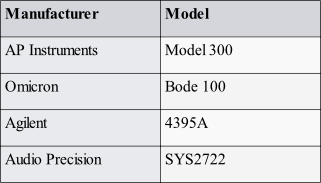
Table 1. List of network analyzers
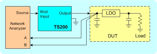
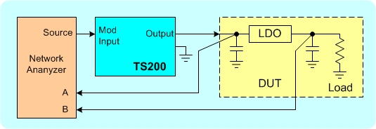
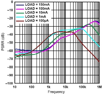
Figure 3. Example of LDO PSRR vs. frequency at various load current.
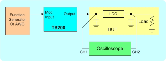

Figure 1. Conventional LDO PSRR test setup is limited to no load or light load.
To test LDO PSRR at heavy load, a high current driver is needed. The TS200 Modulated Power Supply is extremely useful for power supply rejection measurement for such devices as LDOs and power amplifiers. Figure 2 shows how to measure PSRR. PSRR measurement technique involves a network analyzer, the TS200 power amplifier, and the device under test (DUT).
(a)
(b)
Figure 2. LDO PSRR measurement setup. (a) calibration the setup, (b) Measuring LDO PSRR.
Figure 2 shows the LDO power supply rejection ratio measurement setup. Using a network analyzer, the source is connected to the TS200 modulation input. The TS200 DC and AC output is connected to the LDO supply input. It is recommended to reduce the LDO input capacitance to minimum. Since the TS200 can drive heavy load, thus the LDO output can be loaded with the desired loading resistor (i.e. maximum specified load).
Set the TS200 modulation input to AC-
First the analyzer and the TS200 need to be calibrated. Figure 2a shows the calibration setup. The analyzer input-
After calibration, LDO PSRR measurement setup is shown Figure 2b. The network analyzer input-
Figure 4. LDO PSRR testing using an oscilloscope if network analyzer is not available.
Connect a function generator to the TS200 Modulation input. Set the function generator output to 200mVpp sinewave or 20mV if B-
Using the oscilloscope, you can measure the amplitude voltage at CH1 and CH2. Divide CH2 by CH1 is the PSRR. You can use the below equation for PSRR calculation in dB.
PSRR = 20log(CH2/CH1)
If PSRR is better than 40dB, it is recommended to increase the TS200 output ripple voltage 500mVpp due to oscilloscope has lower sensitivity than network analyzer.

