


Instruments For Testing Your Innovations


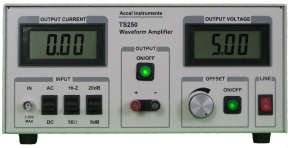
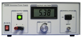
Amplifier power supply rejection ratio or PSRR is typically measured with a network analyzer. In the case of high power amplifier requires high current and most network analyzer output impedance is 50 ohm and cannot drive high current. The TS200 Modulated Power Supply is ideal for amplifier power supply rejection ratio measurements. These amplifiers are include op-amp, audio amplifiers (class-A, B, AB, D and G), differential amplifier, and instrumentation amplifier. TS200 can also measure PSRR for unity gain buffer, digital-to-analog converter, analog-to-digital converter.
Amplifier PSRR measurement is same as LDO PSRR except for a few minor differences. Please see Figure 1 and refer to the “How to Measure LDO PSRR” App Note for additional PSRR measurement details.
Op-Amp PSRR Measurement is Easy
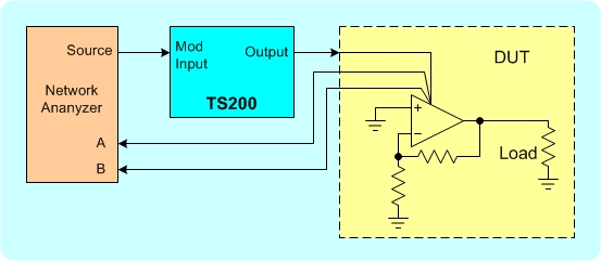
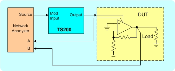
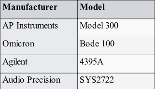
Table 1. List of network analyzers
Figure 1. PSRR measurement setup for amplifier. (a) Calibration setup, (b) PSRR test setup.
(a )
As shown in Figure 1 the amplifier input is grounded, either AC or DC ground, for power supply rejection ratio measurement. Calibrate the setup as shown in Figure 1a with the network analyzer input-A and input-B connected to the same point at the amplifier’s power supply input. After calibration, move input-B to the amplifier output as shown in Figure 1b. Then measure PSRR in the same way as LDO PSRR in the app note.
(b )
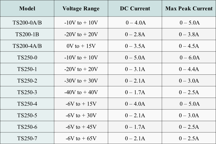
Table 1. PSRR Test Driver Power Amplifier Selection Guide

PDF Version of this App Note


Quick Links

Copyright: Op-