Ask Us Questions

Request a Quote

Technical Info Download Contact

Instruments For Testing Your Innovations

Visit the TS250 page

AC magnetic field is generated by the TS250 high-current amplifier driver.

AC Magnetic Field

AC magnetic field is generated when an alternating current is passing through a coil. The AC current is a time-varying current and it is often a sine-wave. Thus, the magnetic is also time-varying. There are several techniques for generating high-frequency magnetic field as discussed below. The magnetic field intensity or strength is depended on the alternating current. Therefore high-current is needed to produce high AC magnetic field.

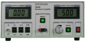
An AC current driver such as the TS200 and the TS250 can output many amperes of current through an AC magnetic coil to produce the electromagnetic field. The TS20/TS250 can drive coils such an AC Helmholtz coil pair directly. This called the direct-drive method as discussed below. High current can be driven through the coil as shown in Figure 1.

Figure 1. The TS250 driver amplifies current and drives a magnetic coil to produce AC magnetic field.

AC Magnetic Field Generation Diagram

High-frequency AC magnetic field is produced by connecting a driver to a coil.

Table 1. AC Magnetic Field Driver Selection Guide

Model

Voltage Range

Peak Reactive Current (Note 1)

Peak Resistive Current (Note 2)

TS250-0

-10V to + 10V

0 – 5.0A

 0 – 6.0A

TS250-1

-20V to + 20V

0 – 3.1A

0 – 4.4A

TS250-2

-30V to + 30V

0 – 2.1A

0 – 3.0A

TS250-3

-40V to + 40V

0 – 1.7A

0 – 2.5A

The TS200 and the TS250 are high-current amplifier and drivers for generating AC or alternating magnetic field. They differentiate from other amplifier instruments in the market, because they  output very high current even at high AC frequencies. Table 1 lists the two (TS250/TS200) alternating magnetic coil drivers’ output voltage and current range.

Low Frequency Electromagnetic Field

Equation-1

AC electromagnet (magnetic coil) impedance is given in Equation-1. In Equation-1 the coil resistance is R and the reactance is jωL. To calculating the electromagnetic coil current, the impedance magnitude or the absolute value is used as in Equation-2. If the coil resistance is small compared to its reactance, resistance sometimes can be ignored. The current through the coil, I, is equal to the voltage, V, divided by its impedance, |Z|, as given in Equation-3.

AC Electromagnet Current and Impedance

 Z=R + jωL

Equation-2

AC magnetic coil impedance is calculated over frequency. Alternating magnetic coil current is calculated over the frequency.

Equation-3

At low frequency the magnetic coil impedance (Equation-2) is usually low, especially when the resistance is also a low value. High current can be obtained even with low voltage as given in Equation-3. For example, if a given Helmholtz coil resistance is 0.1 ohm and the reactance at 60Hz is 1 ohm, the absolute impedance is about 1 ohm. If 5A current is needed, a 5V driver is required. At low frequency, high current can be driven through the coil as shown in Figure 1.

High Frequency Magnetic Field

At high frequency on the other hand, the AC electromagnetic coil impedance is increased proportional to the frequency, ω. The magnetic coil impedance is often very large. Generally, the reactance dominates the overall impedance. For example, an 1mH high-frequency solenoid coil at 10kHz will have a reactance of 62.8 ohm. If 5A current is needed, a 314V driver is required. Thus at high frequency, the coil current is decreased as the frequency increases (Equation-3). Advance resonant impedance-cancellation technique can be used to reduce the driver voltage.

Selecting an Alternating Magnetic Field Generator

Alternating Magnetic Field Driver Waveform Examples

Figure 2. TS250-0 outputs 12App (+/-6A) current for generating alternating electromagnetic field. The TS250 output voltage is 12Vpp with 1 ohm load or 12App.

TS250-0 AC driver amplifier is for generating alternating magnetic field.

Note 1. Magnetic coil is inductive which means its power is reactive. The TS250 output current is reduced for reactive power.

Note 2. Maximum resistive current is obtained at max voltage minus 1.0V. For example 9.0V for the TS250-0.

Using two TS250 drivers to doubles the alternating current magnetic field.

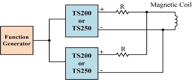
Figure 4. Connect two TS250 in parallel to increase the output current by 2x.

High-Current Amplifier Impedance Matching

Magnetic coils are highly inductive. Their impedance is reactive which means the real part of the impedance is nearly zero (very low resistance) as discussed in Equation-1. Helmholtz coils for example, it does not dissipate real (thermal) power if its resistance is very small. It also means all real power (heat) is dissipated inside the AC magnetic coil driver. As a result there will be excess heating inside the high-current amplifier driver. The TS250 and TS200 can handle about 50 watt RMS reactive power.

Parallel AC Drivers For Higher Current

The TS250-0 high-current amplifier in Table-1 can output up to 6A peak current for producing AC electromagnetic field. Two or three TS250/TS200 can be paralleled connected to increase the AC magnetic driver output current. As shown in Figure 4, each coil power amplifier driver is connected to a small series isolation resistor. The resistance is typically between 0.25 ohm to 1 ohm. You can use the isolation resistor as impedance matching discussed above. Contact factory for more information on parallel connection and high output current driver.

Understand Reactive vs. Real Power

A simple method to increase an electromagnetic driver output current (and stronger AC magnetic field) is to make the coil more resistive. To do that just add a resistor in series with the coil as shown in Figure 3. Use a resistor with resistance between 0.5Z to Z, where Z is equal to the high-frequency coil’s reactance or jωL. As an example, if the AC coil reactive impedance is 10j ohm at 1kHz, use a 5 ohm to 10 ohm series resistor. The combined impedance is given in Equation-4. At high current, the series resistor can dissipate high power. The power dissipation of the series resistor is given in Equation-5. The resistor may be hot at high current. You must choose a power resistor that is rated for the power dissipation. For high frequency applications, select a non-inductive series resistor.

Resistive Impedance Matching

AC magnetic coil amplifier driver impedance matchings is using a series resistor.

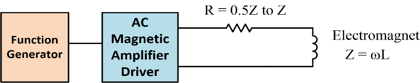
Figure 3. Impedance matching will increase the AC electromagnetic field driver output current.

Calculate the AC electromagnet total impedance using this equation.

Equation-4

Thermal power dissipated in AC magnetic coil resistance when generating alternating current magnetic field.

Equation-5

AC Helmholtz Coil Field

Strong Magnetic Field Using a New Resonant

Series Resonant for High-Frequency Electromagnet

AC Magnetic Coil Design Resources

Resources for Helmholtz Coils Design

Visit TS200 Product Page

TS250 vs. TS200

Visit TS250 Product Page

Ask Us Questions

Quick Links

Related Technical Information

PDF Version of this App Note

TS250 Price List

TS200 Price List

Request a Quote

AC magnetic field calculator

AC magnetic field calculator