Instruments For Testing Your Innovations


Introduction
Helmholtz coil is named after the German physicist Hermann von Helmholtz. It is comprised of two identical magnetic coils positioned in parallel to each other, and their centers are aligned in the same x-
Helmholtz Coil
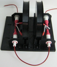
Figure 3. High-
Helmholtz Coil Construction
Since the two electromagnetic coils are identical, uniform magnetic field is obtained when the separation distance is equal to the coil radius. Usually the two coils are connected in series so that equal current is feeding the two coils will create two identical magnetic fields. The two added Helmholtz fields achieve highly uniform magnetic field in a cylindrical volume of space in the center between the two coils. This region of uniform field (cylinder-
High-Frequency AC Helmholtz Coil Model
Helmholtz electromagnetic field is generated by either using Alternating Current (AC) or Direct Current (DC). Majority of Helmholtz coils used for scientific experiments generate static (constant) magnetic fields. Static magnetic field uses Direct Current. In some test and measurement applications require non-
Figure 1. One-axis Helmholtz coil is make of a pair of electromagnetic coils with radius R and separated by a distance also equal to R.
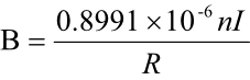
Helmholtz Coil Magnetic Field Calculation
The magnetic field inside the coils in the center is given below for an ideal coil pair (i.e. zero diameter magnetic wire)
Eq. 1
B = Magnetic field in Tesla
n = Number of turns in each coil
I = Coil current in amperes
R = Coil radius in meters


Quick Links
Techniques for Producing High-
A self-
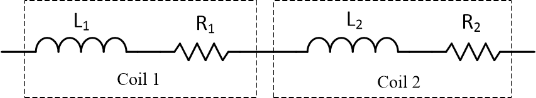
Figure 2. A pair of Helmholtz coils are modeled as two inductors and two resistors in series.
A set of coils can be modeled as shown in Figure 2. Each coil is modeled as a parasitic resistor connected to an inductor in series. The parasitic resistor's resistance is typically very small. For most Helmholtz coil test cases in which the testing frequency is far lower than the self-
If the Helmholtz coil testing frequency is high-
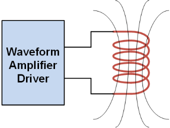
Figure 4. Waveform amplifier directly drives the coils.
AC Helmholtz Coil Driver
There are two ways to generate high-
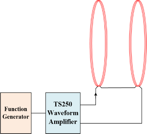
Method 1: Direct-Drive
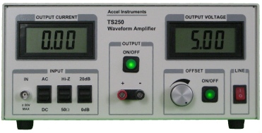
The Helmholtz coils may be driven directly using a current amplifier driver such as the T250 Waveform Amplifier. The direct-
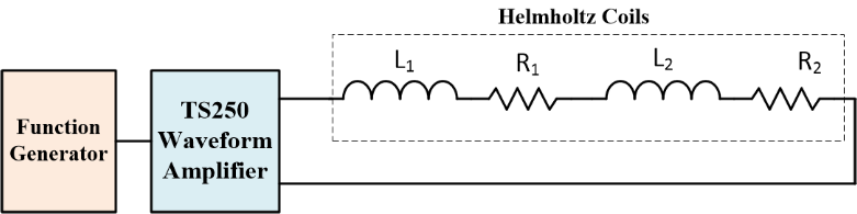
Figure 5. Circuit representation of amplifier directly drives the a pair of Helmholtz coils.
The magnetic field is calculated in the above using Equation 1. The minimum needed voltage to produce the required current can be calculated using Equation 2. Higher inductance (or resistance) or frequency will require higher voltage. For that reason, it is important to design low inductance AC Helmholtz coils. The next step is to drive the Helmholtz coil pair with a high-

I is the peak current
is the angular frequency, = 2πf
L1 + L2 are the total inductance,
R1 + R2 are the total resistance.
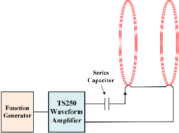
Method 2: Series Resonant
In some scientific experiments, the required electromagnetic field is at high frequency in the range of hundreds of kilo-
Equation 2
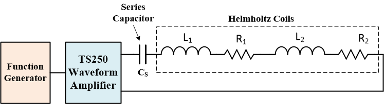
Figure 7. Circuit representation of the Helmholtz coils in resonance using a series capacitor.
As illustrated in Figure 6 and 7, to operate the high-
Equation-

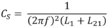
Equation 3
Equation 4
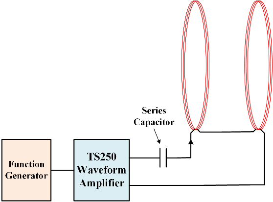
Figure 6. The current amplifier drives high current through the Helmholtz coils using a series resonance capacitor.
Select a Helmholtz Coil Amplifier Driver
After calculating the current and voltage from equation 1 and 2 discussed above, use the Table 1 to select the amplifier model.
Table 1. AC Helmholtz Coil Driver Amplifier Selection Guide
Model |
Voltage Range |
Peak Reactive Current (Note 1) |
Peak Resistive Current (Note 2) |
|
TS200- |
- |
0 – 2.8A |
0 – 3.8A |
|
TS250- |
- |
0 – 5.0A |
0 – 6.0A |
|
TS250- |
- |
0 – 3.1A |
0 – 4.4A |
|
TS250- |
- |
0 – 2.1A |
0 – 3.0A |
|
TS250- |
- |
0 – 1.7A |
0 – 2.5A |
Caution: Potential Electrical Shock
AC Helmholtz coils and capacitor discussed above may contained enough electrical charge and energy to become an electrical shock hazard. High-
Copyright: Helmholtz Coil

Helmholtz Coil For Sale Manufactures and Vendors
Resources for Helmholtz Coil Design
High-


Quick Links

Related Technical Information

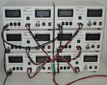
Figure 8 shows an example of an AC Helmholtz coil system using the series resonance method. From the left, a signal generator produces the sinewave. Five high-
Figure 8. Custom-
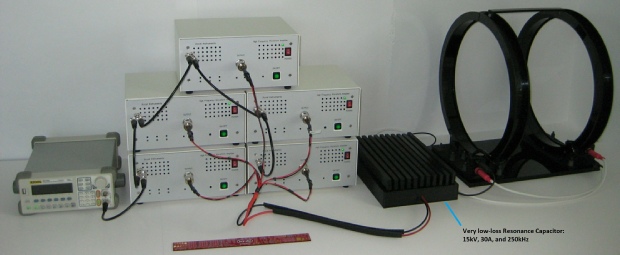
High Frequency AC Helmholtz Coil System Using Resonance