Instruments For Testing Your Innovations


Lab Amplifier
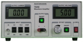
Figure 1. TS250 Waveform Amplifier is used as a lab amp.
Lab Amplifier Connection
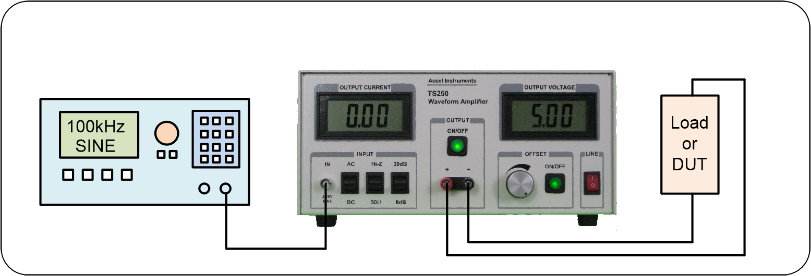
Function Generator
Table 1. High-Voltage Lab Power Amp Selection Guide
Model |
Voltage Range |
DC Current |
Max Peak Current |
|
TS200- |
- |
0 – 4.0A |
0 – 5.0A |
|
TS200- |
- |
0 – 2.8A |
0 – 3.8A |
|
TS200- |
0V to + 15V |
0 – 3.5A |
0 – 4.5A |
|
TS250- |
- |
0 – 5.0A |
0 – 6.0A |
|
TS250- |
- |
0 – 3.1A |
0 – 4.4A |
|
TS250- |
- |
0 – 2.1A |
0 – 3.0A |
|
TS250- |
- |
0 – 1.7A |
0 – 2.5A |
|
TS250- |
- |
0 – 4.0A |
0 – 5.0A |
|
TS250- |
- |
0 – 2.1A |
0 – 3.0A |
|
TS250- |
- |
0 – 1.7A |
0 – 2.5A |
|
TS250- |
- |
0 – 2.1A |
0 – 2.5A |
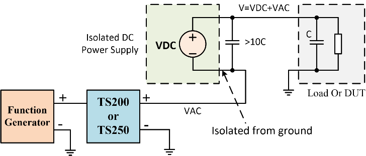
Figure 6. An external isolated DC voltage supply combined with a laboratory amplifier achieve high voltage signal generator.


Quick Links
Copyright: Lab Amplifier
Select a Function Generator
Our lab amplifiers are designed to work with commonly available signal generators and function generators. Laboratory amplifiers signal inputs are designed with standard BNC female connectors. Standard 50-
|
Manufacture |
Model |
Features |
|
Rigol |
DG1022 |
Low- |
|
BK Precision |
4014B |
Low- |
|
Tektronix |
AFG1000 |
|
|
Keysight |
33220A |
20MHz |
|
Keysight |
33250A |
Variable slew- |
Table 2. Function Generator Selection Guide

Lab amplifier is being used in many R&D (research and development) labs. A laboratory amplifier can amplify voltage, or current, or power, or any combination. Some examples of laboratory amps are driving high-
Voltage Gain
Lab Amplifier as Companion to Function Generator
Many lab experiments require waveforms that are high voltage or high current or high power. Although most research labs have function generator for the purpose of generating such waveforms. However, most function and signal generators are unable to fulfill some of these requirements. These generators' output resistance are 50 ohm. They are designed to connect to 50 ohm coaxial cables and terminate into 50 ohm loads. This 50 ohm output resistance severely limits its output current to about 100mA (5V into 50 ohm). For lab bench testing, our function-
Our waveform amplifier products such as the TS250 have very low output resistance (~50 mOhm). This allows it to drive very low resistance loads. Their output current is up to 6A, depends on the model. See the Selection Guide below for output current and voltage range. As shown in Figure 1, a lab amplifier is an ideal companion instrument for producing high power or current or voltage for many scientific and research experiments.
Most available voltage sources for laboratory test applications are often low-
Current Gain
Our lab amplifiers feature input unity gain. In this mode, lab amplifier boosts the current, but not the voltage. Many voltage signal and sources does not have the current capability to drive heavy (high current) load. These voltage sources are either have high source impedance which results in high voltage drop when loaded, or low output current capability. Function generator, for example, has 50 ohm output impedance. Some other voltage signal sources have low output impedance, but are not design to output high current. When loaded with low resistance, its output active devices will not able to support high current and causing the output to collapse. Therefore these signals need high current laboratory amplifiers.
The TS200 and TS250 fulfill many testing applications require high current to drive their low-
Power Gain
In addition to current and voltage gain, power gain is also important is some applications. Output power is maximize when both the current and voltage are maximum for a given resistive load. Our laboratory power amplifiers specify a maximum output voltage and current. If available, choose a load resistance such that lab power amplifier outputs maximum voltage and current. This will result in maximum power output to the load.
Laboratory Amp Usages and Applications
In addition to current and voltage gain, power gain is also important is some applications. Output power is maximize when both the current and voltage are maximum for a given resistive load. Our laboratory power amplifiers specify a maximum output voltage and current. If available, choose a load resistance such that lab power amplifier outputs maximum voltage and current. This will result in maximum power output to the load.
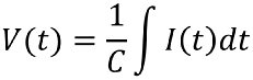
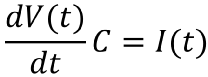
Piezoelectric Transducer Driver
Laboratory amplifier is perfect for driving large-
For instance, for a 3.3uF piezoelectric actuator that requires 20V peak voltage and 10kHz test frequency, the required peak current is 4.14A. In this case a very high-
I=V/Z=V/|1/jωC| =VωC
Equation-
Driving Magnetic Coils
Many laboratory and scientific experiments required time-
The coil drivers such as the T200 and the T250 can output high-
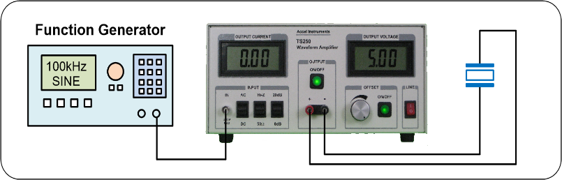
Figure 2. The TS250 lab amp for driving piezoelectric transducer.
Low Frequency and Direct-Drive
The coil impedance is proportional to the inductance and frequency. When the frequency is low, the coil impedance is usually low, especially if its resistance and inductance are also low (Equation-
Figure 3. Magnetic coil is driven by a high-current laboratory amp.

High Frequency and Resonant Method
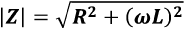
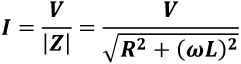
At higher frequency the AC magnetic coil reactance (or impedance) is increased proportional to the angular frequency, ω. The electromagnetic solenoid/coil impedance is usually very high. In generally, at high-
In Figure 4 a series capacitor is connected with AC magnetic coil to operate in resonance mode. The capacitor's impedance polarity is opposite to the coil's impedance. As a result the capacitor becomes an impedance cancellation component. It reduces the overall reactance. At resonant frequency the electromagnetic coil reactance completely cancels the series capacitor reactance. The only thing remains is the magnetic coil parasitic resistance which usually small value. This resonant technique enables the laboratory amp to drive very high current through the coil. Because resonant occurred in narrow frequency range, the drawback of this technique is different test frequency requires different capacitance. Calculating of resonant frequency and capacitor value are detailed in the Resonant Technique Article.
Equation-
Z=R + jωL
Equation-
Equation-
Noise and Transient Simulation
Another common application of the lab amplifier is to simulate power supply noise and transient to stress test subsystems and modules. An example of such test is to simulate automotive cold crank battery voltage waveform. During car engine cranking the battery voltage that supplies all subsystem in the car suffers severe voltage transient and fluctuation. The nominal 12V battery voltage can drop as low as 3 volt in 5ms and spike to as high as tens of volts during a load dump. Our family of waveform amplifiers are ideal for simulating such transient voltage for stress testing devices and subsystems.
Figure 1 above shows the basic setup. Using an external arbitrary signal generator to program the transient (cold crank) voltage profile. Since signal generator outputs maximum 5V into 50 ohm and if transient voltage is higher than 5V, se the lab amp voltage gain feature to boost the voltage. Use the gain of 10 (20dB) setting.
Calculate Transient Current
Most unit-
The first step is to determine the unit-
Equation-
Equation-
Equation-
Advanced Lab Amplifier Techniques
Our series of lab amplifiers already outputs high current. If higher current is needed, multiple lab amps can be connected in parallel. In some scientific experiments such magnetic coil, very high current is needed. Figure 5 below is an example of two TS250 laboratory amplifiers can be connected together to boost the current output. Connecting amps in parallel will also reduce the total output impedance. Three or even four amplifiers can be connected in parallel for very high current test applications. For parallel connecting laboratory power amplifiers, each output needs a resistor to isolate from each other. 0.1 ohm to 1.0 ohm series resistance is typically used. It is recommended the voltage drop across resistors is between 200mV to 1000mV at peak current. For example, the TS250-
Parallel Laboratory Amplifier Connection

Figure 4. AC magnetic coil is modeled as an inductance and resistor. The series capacitor cancels the coil impedance.

Figure 5. High-current is obtained using two waveform amplifier connected together.
Some lab bench test applications require large DC voltage and AC waveform. Power supply ripple rejection testing for example, the DC voltage could be as high as 100V, while the ripple noise voltage is only 1Vpp or so. If the device-
To overcome the above mentioned shortcoming, you can use a laboratory amplifier and an isolated DC power supply to achieve such a high current, high voltage, and high power function generator. As illustrated in Figure 6, our high-
The external capacitor(s) connected across the power supply enables a low-
Combine DC Voltage and Lab Amplifier