


Instruments For Testing Your Innovations


Relay Testing Techniques
Relays are electromechanical devices found in many electronic systems. It is basically a switch, but actuate by electrical current. It consisted of a magnetic solenoid coil, an armature which is part of the switch.
During product development and qualification phase relay must be thoroughly tested. There are a number of AC electrical and timing specifications that must be tested. These test parameters are: operate-
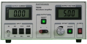
The relays coil often in the 12V, 24V, or higher. In addition, the driving current may be any where from 10mA to over 100mA. Due high voltage and large current, typical lab function generator are not able meet the test requirements. To overcome generators limitation, a Waveform Amplifier is used to amplifier the voltage and provide the necessary current.
Table 1. Relay Test Driver Selection Guide
Model |
Voltage Range |
Peak Reactive Current (Note 1) |
Peak Resistive Current (Note 2) |
|
TS200- |
- |
0 – 4.0A |
0 – 5.0A |
|
TS200- |
- |
0 – 2.8A |
0 – 3.8A |
|
TS200- |
0V to + 15V |
0 – 3.5A |
0 – 4.5A |
|
TS250- |
- |
0 – 5.0A |
0 – 6.0A |
|
TS250- |
- |
0 – 3.1A |
0 – 4.4A |
|
TS250- |
- |
0 – 2.1A |
0 – 3.0A |
|
TS250- |
- |
0 – 1.7A |
0 – 2.5A |
|
TS250- |
- |
0 – 4.0A |
0 – 5.0A |
|
TS250- |
- |
0 – 2.1A |
0 – 3.0A |
|
TS250- |
- |
0 – 1.7A |
0 – 2.5A |
|
TS250- |
- |
0 – 2.1A |
0 – 2.5A |
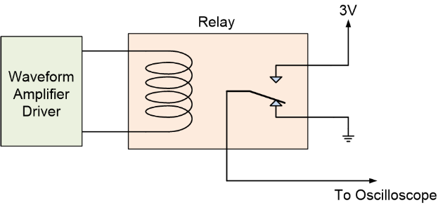
Figure 1 shows an example relay test setup. In this test example, the relay is single-
To test the operate time, a high-

AC Magneti Field Using a New Resonant
Series Resonant for High-

Request a Quote

Quick Links

Related Technical Information
Copyright: Relay Testing

PDF Version of this App Note
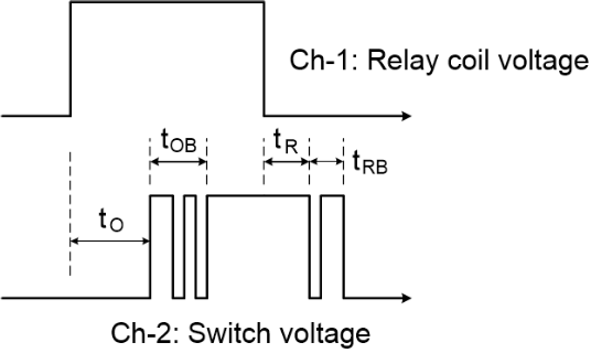
tO is the operate time
tR is the release time
tOB is the operate bounce time
tRB is the release bounce time