


Instruments For Testing Your Innovations


Piezo Driver
High-
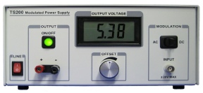
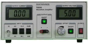
Figure 1. The wideband waveform amplifier is used for high frequency piezo driver.
Calculating Piezoelectric Driver Current
Piezo Driver Connection
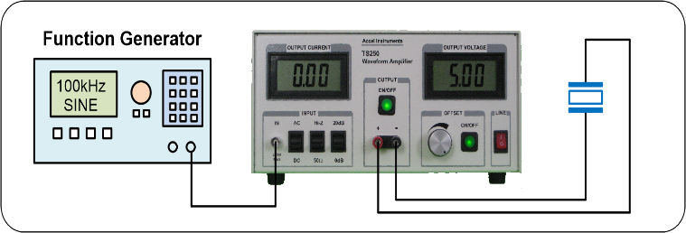
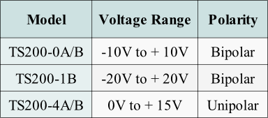
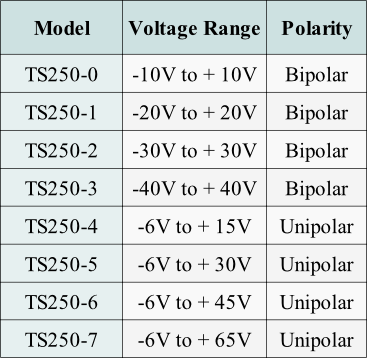
Table 1. High frequency piezo driver Selection Guide
The second type of piezoelectric elements require the highest peak voltage possible and usually positive voltage only. Such examples include PZT motor and stage, actuator and stack, bimorph, etc. These type of transducers general require a voltage range from 0V to a maximum positive voltage (i.e. +60V) and no negative voltage. Use Table 1 to select a unipolar piezo transducer driver.
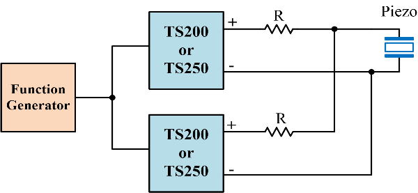
Figure 3. Parallel two piezo driver amplifiers increases the output current by 2x, or increase power by 4x.
Note 1. Piezo element is capacitive which means their power is reactive. The TS250 output current is adjusted for reactive power.
Note 2. Peak resistive current is specified at maximum voltage minus 1V. For exmaple 19V for the TS250-
High Power Piezo Transducer driver Use Multiple Units
Our high power piezo transducer driver are able to output high current and high voltage, thus high power. To further increase the piezo driver amplifier output power/current, 2 or three or more units may be parallel connected. To do so, each PZT transducer driver is isolated from one other with a series resistor as shown in Figure 3. Typically the resistance is between 0.5 ohm and 2 ohm. However, the series resistor may be uses as resistive matching. In that case, the resistance may be increase to higher value as discussion in the previous section "High Frequency Piezo Driver Impedance Matching".
Most piezoelectric (PZT for short) actuators/transducers require higher voltage than most signal generator can supply. For example, a PZT transducer drive voltage is typically more than 10Vpp and the voltage can easily require up to 100V or higher. Most available function generator output voltage are less than 5V into 50 ohm load. Such low voltage is not enough to drive piezoelectric elements. Thus a high current, high frequency, and high voltage piezo driver amplifier is required. For example, a pzt motor needs a 40Vpp pulse waveform to operate, but most signal generator can only output 5V or less. Already depicted in Figure 1, the driver amplifies the signal from the function generator and outputs high voltage yet high-
I=V/Z=V/|1/jωC| =ωVC=2πfVC
Equation-
The current required to drive the piezo transducers is determine using Ohm's law. The piezo element current is proportional to the frequency, voltage, and capacitance as in Equation 1. From Equation 1, V is the voltage, I is the current, C is the piezoelectric capacitance, and f is the frequency.
High Voltage and Power PZT Driver

Figure 2. Using a series resistor to increase the piezo driver amplifier output current and power.
Equation-

Equation-


Quick Links

Related Technical Information
Copyright: Piezo Driver

PDF Version of this App Note
As an example, for a high-
Determine Voltage Requirements
It is crucial to understand the required voltage for proper piezoelectric transducer operation in order to select the optimal PZT driver amplifier. This usually involve careful understand the piezoelectric device voltage specifications. There are generally two types of voltage requirements: bipolar and unipolar.
Bipolar:
PZT devices that requires a given peak-
Unipolar:
Determine the Power Drive Requirement
Capacitive PZT Devices:
Most PZT transducers are highly capacitive, some actually resistive at the resonant frequency which will discuss in the next section. For capacitive PZT devices, it only require the piezoelectric driver to output a voltage amplitude as discussed above. It does not care about current or power. However it require certain amount of current to drive it at the desired voltage and frequency. The current requirement was discussed above in Equation 1. The higher the frequency, capacitance, or voltage, or any combination, the higher the current is needed. The power required for driving capacitive type PZTs are reactive. This means no power is absorb by the sensor/transducer. All power are dissipated in the driver itself in the form of heat. See Impedance Matching section below for further details.
Resistive Device Type:
The second type of PZT-
High Frequency Piezo Driver Impedance Matching
Reactive Power vs. Real Power
The above section discussed most high-
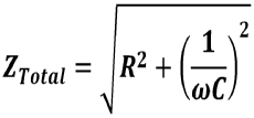
Piezo Driver Amplifier Resistive Matching
One way to reduce the piezoelectric driver self-
Resonance Piezo Transducers Driver
As discussed above some PZT elements are resonate at a frequency. At resonance it becomes resistive as opposed to capacitive. Langevin ultrasonic transducer and piezo horn are examples of these devices. The common applications include ultrasonic cleaning and washing, levitation, and vibration. The most common resonant frequency is 40kHz. These resonance PZT usually specify its power rating and a resistance range. They don't normally specified the voltage range. As an example, an ultrasonic transducer spec sheet indicates its resistance range is 15-
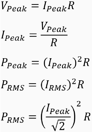
Use Equation 4 -
Equation-
Equation-
Equation-
Equation-
Equation-
Stepe 1: Using Equation 5 to divide the driver maximum peak voltage by the transducer's specified maximum resistance. This is the PZT's maximum current. Make sure the PZT current is still within the driver's specified peak current. If the PZT current is higher than the amplifier specified maximum current, then use the amplifier's max peak current instead.
Step 2: Use Equation 6 to calculate the peak power. The current is calculated in Step 1. The resistance is the maximum specified resistance from Step 1. This is the peak power. Use Equation 8 to calculate the RMS power.
Step 3: Repeat Step 1 and Step 2 with the minimum pzt specified resistance.
Due to the piezoelectric transducer specified resistance is in a range, the optimal maximum power driver for the maximum resistance may be different from the driver for the minimum resistance. In this case you may choose the one with the highest voltage, because you may parallel connect two piezo amplifier drivers to obtain higher power as shown in Figure 3.
Let's use the below example. A PZT ultrasound transducer is specified with resistance range of 15 to 20 ohm at 40kHz resonance frequency. Using Step 1, maximum resistance of 20 ohm, and Table 1, the calculated peak current is 2A using the TS250-
Using Step 3 to repeat the calculation using the 15 ohm minimum resistance. The maximum current is 40V/15ohm = 2.67A which is higher than the maximum 2.5A current. So 2.5A peak current is used. The peak and RMS power is 93.75W and 46.9W, respectively.
Advance Techniques
High voltage amplifier piezo driver
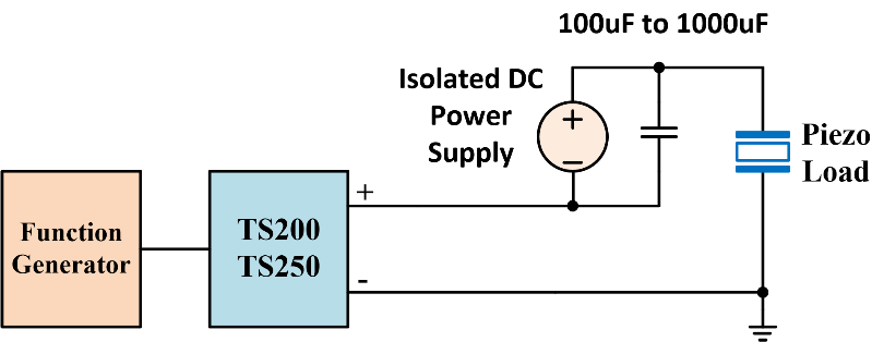
If the piezoelectric device requires unipolar (only positive) voltage, Figure 4 below uses a DC bias voltage to obtain voltage up to 80V while can output high current at operating at high frequency. For instant, an actuator requires a sinewave voltage from 0V to 80V. Using the circuit in Figure 4, the isolated DC voltage supply provides the bias while the waveform power amplifier TS250 provide the 80Vpp signal. Using this method, the PZT driver able to produce high current and high power (reactive or real), up to peak power of 200 watt (2.5A * 80V = 200W).
Figure 4. This setup forms a high voltage amplifier piezo driver that can output up to 80V and 200 watts.
Important notes for the setup in Figure 4. The TS250 high voltage piezo driver's negative output terminal must be connected to the ground node. The ground node must be common with the function/signal generator ground as well as the pzt element. DC supplies have internal capacitors already. It is still required to add external capacitors for bypassing. This is particularly important for high frequency piezo elements. Multiple capacitors parallel connected is recommended. It is important to use ceramic capacitors with low ESL and ESR. Other capacitor types, such as tantalum and electrolytic may be acceptable. Total external capacitance must be high enough so that its impedance is lower than the piezoelectric impedance. Important note: Do not accidently short the piezo device (load). By doing so is equivalent to connect a negative 80V to the TS250 output which will cause damage!
Transformer Boost High Voltage
Another technique for boost higher voltage is using a wideband transformer. As shown in Figure 5 the transformer turn ratio is 1:N. The secondary-

Figure 5. Using transformer to boost the voltage to over 200V.