


Instruments For Testing Your Innovations


Magnetic Coil Cutoff Frequency Calculation For Current Source
There are application cases where current source is desirable. Current source is useful for maintaining constant current amplitude while the load impedance is change over frequency (or voltage or temperature). A perfect example is producing fixed AC magnetic field (constant current) over a frequency range. When using current source, the frequency response is very different from that of the traditional voltage-
The cutoff frequencies of analog circuits for current source is different from that of voltage source. Figure 1 shows a simplified current-
The voltage across a load is governed by Ohm's law giving in Equation 1. The I is the current, the Z is the impedance. For an inductive load such as AC magnetic coils, whose impedance is jωL. ω is the angular frequency or 2πf, and L is the inductance. Since we are calculating the magnitude, we will ignore the phase j. Equation 1 becomes Equation 2 for an inductive load such as Helmholtz coil set for example. Since ω = 2πf, Equation 3 is the voltage across the inductive load. Rearrange Equation 3 to solve for the frequency and the result is shown in Equation 4.
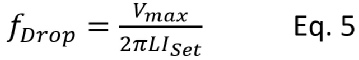
The current source driver has limited voltage range (compliance voltage range), and it also has a maximum output current limit (compliance current range). After inserting the maximum voltage and the desired set current, the maximum frequency without limited by voltage is given in Equation 5. This is also called the dropout frequency. ISet is set current or the regulated current at low-
Table 1. Magnetic Coil Driver Selection Guide
Model |
Voltage Range |
Peak Reactive Current (Note 1) |
Peak Resistive Current (Note 2) |
|
TS200- |
- |
0 – 4.0A |
0 – 5.0A |
|
TS200- |
- |
0 – 2.8A |
0 – 3.8A |
|
TS200- |
0V to + 15V |
0 – 3.5A |
0 – 4.5A |
|
TS250- |
- |
0 – 5.0A |
0 – 6.0A |
|
TS250- |
- |
0 – 3.1A |
0 – 4.4A |
|
TS250- |
- |
0 – 2.1A |
0 – 3.0A |
|
TS250- |
- |
0 – 1.7A |
0 – 2.5A |
|
TS250- |
- |
0 – 4.0A |
0 – 5.0A |
|
TS250- |
- |
0 – 2.1A |
0 – 3.0A |
|
TS250- |
- |
0 – 1.7A |
0 – 2.5A |
|
TS250- |
- |
0 – 2.1A |
0 – 2.5A |

Helmholtz Coil Pair For Producing Uniform Field
Calculating Magnetic Field for Solenoid and Coil
Strong Magneti Field Using a Current-


Quick Links

Related Technical Information

PDF Version of this App Note

Any higher frequency than the dropout frequency will cause current to go out-
At the dropout frequency, the current is still output at 100% of the set current. The traditional corner (3dB) frequency definition for a voltage source is when the frequency reach to a point where output voltage is reduced by a factor of 1/√2 or about 0.707 of the "expected" value. To use this definition and apply to a current source driver, Equation 3 is reused as shown in Equation 6. Equation-

Equation 8 is setup to solve the cutoff (-
The above equations and discussions are for inductors (electromagnetic coils, solenoids, Helmholtz coils, relays, motors, etc.). Plotting Eq-
In conclusion, this application note shows that for current-
The voltage across a load is governed by Ohm's law giving in Equation 1. The I is the current, the Z is the impedance. For an inductive load such as AC magnetic coils, whose impedance is jωL. ω is the angular frequency or 2πf, and L is the inductance. Since we are calculating the magnitude, we will ignore the phase j. Equation 1 becomes Equation 2 for an inductive load such as Helmholtz coil pair for example. Since ω = 2πf, Equation 3 is the voltage across the inductive load. Rearrange Equation 3 to solve for the frequency and the result is shown in Equation 4.
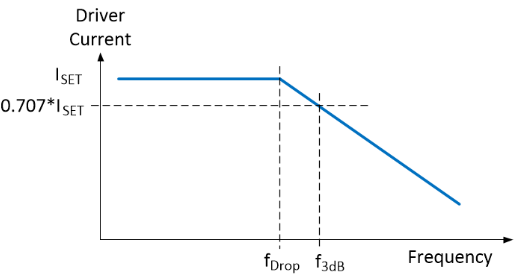
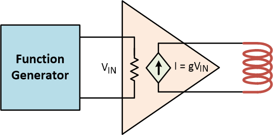
Figure 1. Constant output current driver for driving electromagnetic coil.
Figure 2. Inductive coil frequency response with constant-