


Instruments For Testing Your Innovations


Magnetic Field Calculator for Coils and Solenoids
Figure 1. Cross-
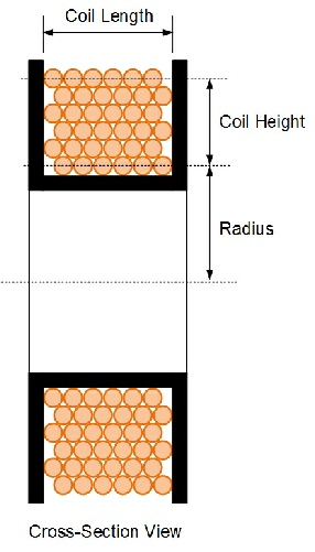
Note1 : Coil copper inner radius from the center to the first layer of copper. Note the copper inner radius is not same as the bobbin inner radius. Copper inner radius must be larger than bobbin inner radius. See Figure 1 for details.
Note 2: Enter the length of the solenoid or coil. This is sometime called coil width. The coil width is same as the bobbin inner width. See Figure 1 for details.
Table 1: Copper wire diameter with coated insulation. Use Table 1 to enter the copper wire diameter.
Table 2: Copper wire diameter WITHOUT coated insulation. This is the bare copper diameter. This diameter is used to calculate the resistance more accurately. Use Table 1 to enter the bare copper wire diameter.
Note 3: Enter the number of turns in the coil or solenoid.
Note 4: Enter the coil current. If the current is AC, this is the peak current.
Note 5: Enter the solenoid/coil operation frequency (sinewave). For DC, just leave the default 1kHz and use the DC parameters calculated below.
Note 6: The calculated magnetic at a distance from the center of the coil, see Figure 2. Enter zero for the magnetic at the center of the coil/solenoid. For example, if the coil bobbin width is 30mm, a distance of 15mm is at the coil edge. Another example, a distance of 25mm means the magnetic field is calculated 10mm outside of the coil (30mm/2+10mm = 25mm).
Note 7: Enter the core relative permeability constant, k. Enter 1 for air core.
Note 8: Enter the coil winding density compact factor. If the coil is wound such that the distance between two copper layers is equal to the diameter (Figure 3), the compact factor is equal 1.0. However, practical wounding is shown in Figure 4. This is the most tightly wound with no space wasted. The ideal compact factor is 0.866. A practical compact factor range is 0.88 to 1.0. Typical compact factor is 0.9.
Note 9: Calculated magnetic field at a distance from the coil center. See note 6.
Note 10: Calculated coil height. This is the minimum bobbin height.
Note 11: DC coil resistance in Ohm. It is calculated at room temperature. Resistance is further increase at higher temperature.
Note 12: Coil inductance in micro-
Note 13: Total coil impedance magnitude. It is calculated using inductance, frequency, and resistance.
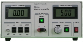
Note 14: This is the minimum voltage needed to drive the coil. It is calculated using DC resistance. Note DC resistance is calculated at room temperature. As resistance is increase at hot, higher voltage is needed. Note higher voltage is need for AC waveform using the an amplifier driver such as the TS250, because resistance increase rapidly at higher frequency.
|
Gauge |
Diameter |
|
10 |
2.67716 |
|
11 |
2.39268 |
|
12 |
2.13868 |
|
13 |
1.91516 |
|
14 |
1.7145 |
|
15 |
1.53162 |
|
16 |
1.36652 |
|
18 |
1.09474 |
|
20 |
0.87884 |
|
Gauge |
Diameter |
|
10 |
2.58826 |
|
11 |
2.30378 |
|
12 |
2.05232 |
|
13 |
1.8288 |
|
14 |
1.628 |
|
15 |
1.45034 |
|
16 |
1.29032 |
|
18 |
1.02362 |
|
20 |
0.8128 |
Table 1. Wire gauge diameter with insulation in mm.
Table 2. Gauge diameter without insulation (bare copper) in mm.
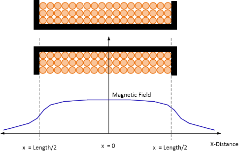
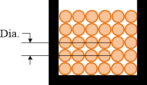
Figure 3. Coil winding spacing factor of one.
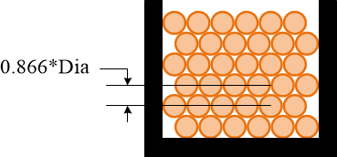
Figure 4. Ideal compact factor. The distance between two layers is 0.866 of diameter.
Figure 2. Calculated magnetic field at distance x from the center.
New advance AC magnetic field calculator - Click here
This calculator uses advance techniques to calculate magnetic field for solenoids and coils. It is the most comprehensive and accurate calculator available. In addition to magnetic field, it also calculates DC resistance, inductance, power dissipation, resonance capacitance, and much more. These important design information are ideal for designing AC magnetic coil and solenoid, especially at high frequency.
Note 15: This is the capacitance needed to form an LC resonant tank. The coil impedance is reduced or canceled using this series resonant capacitor (Figure 5). Click here for more information about series resonant magnetic coil. It is calculated using the coil inductance and the user input frequency.
Note 16: At resonant the voltage across the capacitor may be very large. This is the peak voltage across the capacitor. Therefore this is the minimum capacitor voltage rating. Click here for more information.
Note 17: This is the calculated coil power dissipation (in watts) for the DC current case. High power dissipation will increase the copper wire temperature and the resistance as discussed in Note 11.
Note 18: If the coil is driven by an AC driver such as the TS250, the RMS power dissipation is calculated using the user input (peak) current to calculate the RMS current and then calculate the RMS power. High power dissipation will increase the copper wire temperature and the resistance as discussed Note 11.

Figure 5. High-

Copy right:
Released on: March 2022
Today's date is: