


Instruments For Testing Your Innovations


High-Frequency Electromagnet Using Resonant Technique


Electromagnetic coils such as relays, solenoids, inductors, Helmholtz coils, electromagnets, and electric motors often time required high-
Figure 2. Waveform amplifier drives high current through the coil at resonance.
At high frequency on the other hand, the impedance of a coil or inductor increases with frequency. Z = jL. At high frequency the coil impedance is very high such that high voltage is needed to drive high current through the solenoid coil. For example, at 200kHz the impedance of a 2mH electromagnet will be 2512 ohm. If you drive the electromagnetic coil with 40V for example, you would get about 16mA (40V/2512 ohm = 16mA). For most applications, this is not enough current to produce enough magnetic field. For high magnetic field applications, higher current through the coil is desired. To drive a 1A high-
Figure 3. At resonance the inductor and capacitor impedance cancel each other and act like a short circuit.
To operate the coil in resonance mode, a series capacitor is added as shown in Figure 2. The series capacitor impedance has an opposite polarity than the inductance. Thus the capacitor is acting as an impedance cancellation device. It reduces the total impedance. At resonance the capacitor reactance (imaginary portion of the impedance) is completely cancels the inductor reactance. That is the inductor and capacitor reactance are equal magnitude but opposite polarity. Only the inductor’s parasitic resistance remained. With only resistance remained, the waveform amplifier can drive high-
To further understand impedance cancellation at resonance, consider Figure 3 using 2mH solenoid and 200kHz. At resonance the voltage across the capacitor is -

Figure 1. Waveform amplifier directly drives an inductor coil with a parasitic resistor.
Resonant Technique
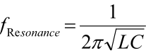
To achieve high-


Capacitor Selection
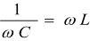
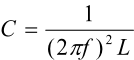
Choose the series capacitor with capacitance such that the capacitor reactance is the same as coil reactance at a given resonant frequency.
Using the above example for 2mH Helmholtz coils and 200kHz operation, the series capacitance is calculated 317pF. The capacitor should be high-
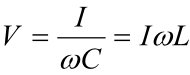
I is the peak current.
Using the above example, the voltage rating must be at least 2.5kV (V = 1A * 2512ohm = 2512V). Add additional voltage rating margin in case higher current is used.
The total resistance is the coil’s AC resistance and the capacitor electric static resistance (ESR) combined. At high frequency the capacitor ESR can be large, sometimes even larger than the coil resistance. Use only low ESR capacitor for resonant technique.
Coil Selection
If you have the ability to choose your own relay coil or design your own coil, consider the follow criteria.
-
o Low resistance to reduce heating and allows higher current
o Consider resistance increases at high frequency due to skin-
-
-
Caution
High-
Table 1. Waveform Amplifier Selection Guide


Quick Links

Related Technical Information
Custom-Made Coil Information
50mm diameter 100kHz Helmholtz coil set
207mm diameter (109mm inner) 20mT Helmholtz coil pair
We offer custom-made coils to meet our client’s specifications. We design and optimize coils and solenoids to produce the maximum magnetic field and operating at the highest possible frequencies. These coils include solenoids and Helmholtz coils for many scientific and research experiments. High frequency magnetic coils are more difficult to design, because of increase in AC resistance and inductance. We consider the coil size, magnetic field, needed driving current, and required frequency. We have a number of coil drivers available such as the TS250 and TS200. Custom-made high current driver is also available. Furthermore we offer complete custom-made solution that include the coil, matching resonant capacitor, and driver.


Gallery And Case Examples
Custom-Made High-frequency Coil Specs:
Coils up to 14 inches (355mm) in diameter.
Copper wire 30 gauge to 10 gauge.
Up to 1MHz frequency range.
Matching resonant capacitor, driver, and harness are available.

175mm diameter 80mT 10kHz Helmholtz coil set

Six TS250-