Technical Info Download Contact

Instruments For Testing Your Innovations

High Current Amplifier

High-current amplifier for amplifying function generator output. It is ideal for amplifying current, voltage, or power.

Visit TS200 Product Page

Visit TS250 Product Page

High output current amplifier for waveforms that is driving heavy loads such as coils, piezo actuators, capacitors, and more.

Ask Us Questions

Request a Quote

High Current Amplifier - Introduction


High current amplifier is a very useful piece of instrument to have in the lab. It is very handy for increasing the current driving capability of a function generator or arbitrary waveform generator. Many laboratory applications require high current amp to drive heavy load. Application for high-current amplifiers include driving heavy resistive load, driving magnetic coil, electrochemical reactor, piezoelectric transducers, and many other applications.


Conventional function generator or signal generator has an output impedance of 50-ohm and they are optimized for driving 50-ohm loads.  If the load impedance is lower than 50-ohm or requires higher current, a current amplifier is needed. The TS200 and the TS250 high-current amplifier are great companion instruments for function generator. This app note will use the TS200 as examples.

Figure 1. Simplified diagram is showing how to amplify signal from a function generator to delivery current to a heavy load.

Function Generator Is Not Strong Enough – The Problem


Function generators are commonly found in laboratories. They are being used for all kinds of tests and experiments. Conventional function generator or signal generator has an output impedance of 50-ohm and they are optimize for driving 50-ohm loads. Their outputs are limited to 5V into 50-ohm or 100mA maximum. For high-current applications, a high current amplifier is required to amplify the driving capability.


Figure 2 and 3 shows how a function generator cannot drive heavy loads. The output impedance of the generator is 50-ohm. The high source resistance attenuates output voltage and limits the output current. For example, the 50-ohm source impedance and 5-ohm load in Figure 2 forms a voltage divider that attenuates the voltage by a factor of 11.

Figure 2. A function generator outputs 0-to-5V square-wave with 50-ohm source impedance driving a low-resistance load (left). The output voltage is attenuated (right).

Figure 4 shows how the TS200/TS250 high current amplifier can drive the above mentioned heavy loads with negligible attenuation, because its source impedance is near zero. The TS200/TS250 current amplifiers has very low output impedance in the order of tens of mili-ohms allowing it to drive heavy loads without attenuation. The output amplitude remains constant up to its rated frequency. Figure 5 shows the TS200 output waveform maintained 5V square-wave when driving a 5-ohm resistor (left) or 1uF capacitor (right). Figure 6 shows the TS200-0A high-current modulated power supply driving a 1-ohm resistive load with 10A peak-to-peak or 5A 0-to-peak.

High Output Current Amplifier – The Solution

Figure 1 - Simplified diagram is showing how to amplify signal from a function generator to delivery high current to a heavy load.A function generator outputs 0-to-5V square-wave with 50-ohm source impedance driving a low-resistance load.Without a high current amplifier, the function generator output voltage is attenuated.A function generator outputs a 0-to-5V square-wave with 50-ohm source impedance. The function generator is driving a capacitive load.A function generator outputs a 0-to-5V square-wave with 50-ohm source impedance.  The function generator is driving an inductive load.A function generator outputs a 0-to-5V square-wave with 50-ohm source impedance.  The function generator is driving a capacitive load. The output waveform is distorted.Without a high current amplifier, the function generator is driving an inductive load, the output waveform is distorted.

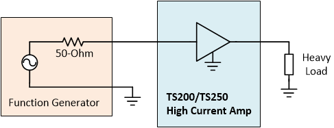
Figure 3. A function generator outputs a 0-to-5V square-wave with 50-ohm source impedance.  Top: The function generator is driving a capacitive load.  The output waveform is distorted.  Bottom: The function generator is driving an inductive load. The output waveform is distorted.

When the load is capacitive (Figure 3 top), the signal generator's source impedance and load capacitance formed a low-pass RC filter. This RC filter distorts waveforms and limits the maximum operating frequency. It is not practical for a function generator or an arbitrary waveform generator to drive a heavy capacitive load. Similarly in the case of inductive loads such as a relay or a magnetic coil, the waveform is also distorted as shown Figure 3 (bottom).

Figure 4.  TS200/TS250 high output current amplifier drives heavy load without voltage attenuation.

TS200 high current amplifier drives high current load without voltage attenuation. High-current amplifier is driving a 5-ohm load. The output waveforms maintained 5V square without any distortion or attenuation. High-current amplifier is driving a 1uF capacitor. The output waveforms maintained 5V square without any distortion or attenuation.

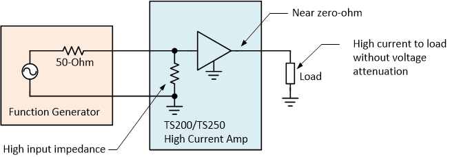
Figure 5. TS200 high-current power amplifier is driving a 5-ohm (left) or a 1uF capacitor (right). The output waveforms maintained 5V square without any distortion or attenuation.

The TS200 high output current amplifier is driving a 4.7mH inductor. The output waveform maintains 5V square without any distortion or attenuation. The high-current lab amplifier is driving a 1-ohm resistor achieving 10A peak-to-peak.

Figure 6. Left: The TS200 is driving a 4.7mH inductor. The output waveform maintains 5V square without any distortion or attenuation. Right: The TS200 amplifier is driving a 1-ohm resistor achieving 10A peak-to-peak.

Current Gain Amplifier

Current-gain amplifier amplifies current but not the voltage. Many voltage signals and sources does not have the current capability to drive heavy (high current) load. These voltage sources have high source impedance which result in large voltage drop when loaded. Function generator, for example, has 50 ohm output impedance. Some other voltage signal sources have low output impedance, but are not design to output high current. When loaded with low impedance, its output active devices will not work. Therefore these signals need a current amplifier.


The TS200 and TS250 fulfill many testing applications that require high AC current to drive their low-impedance load such as coils, piezo, and other devices. These current-gain amplifiers have very low output impedance (50m ohm typical). They can output up to 6A current. See the TS200 and TS250 datasheets for output current capability. Their inputs are selectable either high-impedance or 50 ohm termination. The TS250 features a switch-selectable gain setting. For amplifying current without amplifying voltage, use the 0dB setting. You can also use the 20dB setup that will amplify both current and voltage. The TS200 as a fixed voltage gain of 0dB or 20dB.

Higher Output Current

The TS250/TS200 output current is in the range of 1.4A to 6A, depends on the voltage range. See the datasheet specs for output current range. In some test applications higher current is required. Two or three TS250 current amplifiers may be operate in parallel as shown in Figure 8. The output current is double or triple in proportion to the how many TS250 connected in parallel. Using a series resistor for each current amp to isolate from one other. Typical series resistor resistance is 0.3Ω to 1.0Ω. Use higher resistance for for higher voltage models (i.e. 1 ohm for the +/-40V model). Make sure the isolation resistors are rated to handle the power dissipation.

Connecting two high output current amplifiers to doubles the output current.

Figure 8. Two TS250 current amplifiers connected in parallel increase the current by 2X.

High Current Amplifier Application Examples


High-Current-Amplifier.pdf

PDF Version of this App Note

Visit TS200 Product Page

TS250 vs. TS200

Visit TS250 Product Page

Ask Us Questions

Request a Quote

Quick Links

Copyright: High-Current Amplifier

Function Generator Waveform Amplifier

How to Measure LDO PSRR

Piezoelectric Driver

Maximizing TS200 Output Current

Related App Notes

TS250 Price List

TS200 Price List

Table 1. High-Current Signal Amplifier Selection Guide

Model

Voltage Range

DC Current

Max Peak Current

TS200-0A/B

-10V to + 10V

 0 – 4.0A

 0 – 5.0A

TS200-1B

-20V to + 20V

0 – 2.8A

0 – 3.8A

TS200-4A/B

0V to + 15V

0 – 3.5A

0 – 4.5A

TS250-0

-10V to + 10V

0 – 5.0A

 0 – 6.0A

TS250-1

-20V to + 20V

0 – 3.1A

0 – 4.4A

TS250-2

-30V to + 30V

0 – 2.1A

0 – 3.0A

TS250-3

-40V to + 40V

0 – 1.7A

0 – 2.5A

TS250-4

-6V to + 15V

0 – 4.0A

 0 – 5.0A

TS250-5

-6V to + 30V

0 – 2.1A

0 – 3.0A

TS250-6

-6V to + 45V

0 – 1.7A

0 – 2.5A

TS250-7

-6V to + 65V

0 – 2.1A

0 – 2.5A

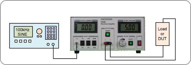
Figure 7. TS250 high output current amplifier is driving a heavy load.

High-Current Amplifier Connection

High current driver is needed to drive low-resistance load.

Function Generator